|
|
Post by richardburton on Jan 27, 2009 13:34:51 GMT 1
W...O....W! That is top notch, MrG!
|
|
|
|
Post by mrgrotey on Jan 27, 2009 14:17:24 GMT 1
Btw the way I should really state the image is not mine, it was made by someone on my 3d forum
|
|
|
|
Post by Lonesome Crow on Jan 27, 2009 21:51:54 GMT 1
I second that wow!  that is a great picture 'mrgrotey' your friend has some serious talent (he doesn't want to help use to design The ultimate Fighting Machine does he? ), the textures and metal highlights look ace. I like the look of the tentacles but they seem a bit too thick, perhaps if we thinned them down a bit lot and made them more whip-like. 'Relyt' I like your design and it put me in mind of the inner shaft of a pump action ratchet screwdriver, I think it could be a winner, in my humble opinion. edit. I am currently working on the leg joints, it's not easy when you can't use fixed or semi-fixed pivots, but I'm getting there. |
|
|
|
Post by Bagnew on Jan 27, 2009 22:21:32 GMT 1
Wow, Mr. G, That's brilliant, but I agree with Mr. F regarding the Thickness of the Tentacles.
Good luck with the leg joints, perhaps something like two magnets holding the two (or more) parts of the legs together and to the body, with struts like hydraulic ones, but using the little metal discs with an elastic sheath covering them which expand and contract to move the leg segment around the magnet? I know it sounds like a pivot, and probably is, but that's just my 2 cents worth.
|
|
|
|
Post by Lonesome Crow on Jan 30, 2009 3:29:57 GMT 1
This is my attempt at one of the leg joints (this is just the joint not the motive power, that will come later) I think it has everything Wells described: it's not a fixed or semi-fixed pivot and it has curved rods that slide over one another, as the side view animation shows.   The thing that came to me whilst I was drawing these pictures was the joints would be very susceptible to dust and dirt so the Martians would probable have the joint encased in protective armour, so you probable wouldn't see anything of the actual joint.  which means I just wasted my time  Bugger it!  |
|
|
|
Post by poyks on Jan 30, 2009 6:02:16 GMT 1
It would work if the slide bearings were made elliptical so the centre shaft of the lower section moved in a sinusoidal curve away from the upper section as the joint angle decreased.
That would keep this great design AND remove the impression of a "fixed pivot".
A sheath as described in the book over the bearings would protect them from dust and dirt.
|
|
|
|
Post by Lonesome Crow on Jan 30, 2009 21:27:56 GMT 1
Good idea. That way when the knee joint bends, it would move forward and down in an ark, I can see it in my head, its getting it down on paper...  I'll get back to you ;D |
|
|
|
Post by crystalegg on Jan 31, 2009 1:01:09 GMT 1
It's not a total waste, as the underlying structure serves as a guide for the design of the flexible covering. How about a texture similar to the striated appearance of muscle tissue ? While it doesn't quite match Wells' descripton, your design is still great. From his description I think Wells design used, instead of your cables, opposed electromagnets in an elastic sheath that did the job of living muscle .
Perhaps your model could use a translucent sheath that still allows your hard work on the mechanism to be seen a bit.
|
|
|
|
Post by Lonesome Crow on Jan 31, 2009 2:21:14 GMT 1
It's not a total waste, as the underlying structure serves as a guide for the design of the flexible covering. How about a texture similar to the striated appearance of muscle tissue ? :-/I don't want to make it too organic. While it doesn't quite match Wells' description, your design is still great. From his description I think Wells design used, instead of your cables, opposed electromagnets in an elastic sheath that did the job of living muscle . :)Oh yes I realize that, I only put the cables in to make the mechanism more understandable and I did say a couple of posts ago "(this is just the joint not the motive power, that will come later)" Perhaps your model could use a translucent sheath that still allows your hard work on the mechanism to be seen a bit. I like this idea.  'Poykes' is this more what you had in mind?  This one's not animated but I think you should be able to imagine its operation, when all the curved rods are stacked one atop another the leg will be straight. |
|
|
|
Post by Bagnew on Jan 31, 2009 5:14:50 GMT 1
That looks like it will make the machine's gait a bit more natural.
|
|
|
|
Post by poyks on Jan 31, 2009 14:49:30 GMT 1
That's exactly what I had in mind! It just needs some kind of strengthening, and/or possibly an opposing mechanical tendon. Nice work!  |
|
|
|
Post by Lonesome Crow on Feb 1, 2009 17:15:55 GMT 1
I've had a go at animating it, I've also had a go at the Disks in an elastic sheath for the musculature.  Looks a bit like an earthworm. ;D |
|
|
|
Post by Bagnew on Feb 1, 2009 19:15:17 GMT 1
Lookin' Good.
Nice worm, too!
|
|
|
|
Post by poyks on Feb 1, 2009 20:23:29 GMT 1
The movement looks great, evolving nicely! |
|
|
|
Post by mrgrotey on Feb 1, 2009 23:53:07 GMT 1
Although its nicely animated and a very interesting concept I cant help seeing the physical impossibilities of that mechanism. The way it is at the moment there is nothing fixed for the lower leg to rotate around. The worm would be pulling up on the 'axle' and just holding it into the plates. Its current fixed pivot point (just above where the axle is) would need to be held in place to allow the axle to rotate the lower leg around it. Im having a hard time spitting out what I mean here but hopefully you understand. I'll have a go to modify it tomorrow as a bit more input than just a 'your doing it wrong blah blah blah. I also get the feeling that this is a very weak structure, especially when at the bent stage. Im not being a dick, I feel crits are far better to progress an idea than saying its great all the time thats all 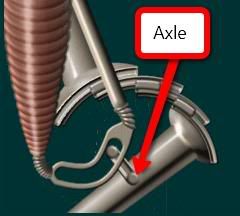 |
|


 that is a great picture 'mrgrotey' your friend has some serious talent (he doesn't want to help use to design The ultimate Fighting Machine does he? ), the textures and metal highlights look ace.

 Bugger it!


